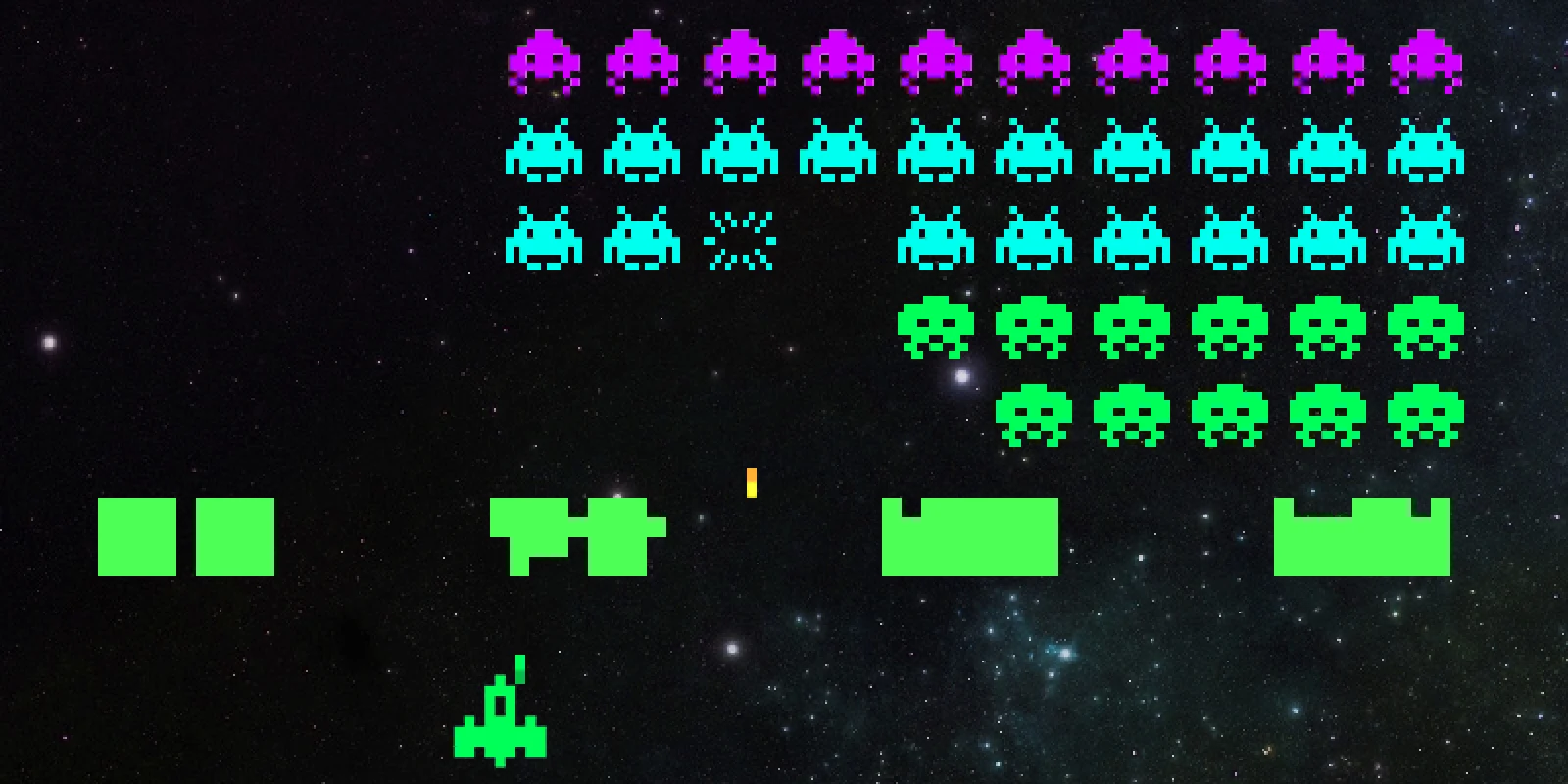
Back in 2015 I gutted a broken Game Boy and squeezed a Raspberry Pi 2 inside it. Four weeks, one sacrificed Pi and a lot of melted plastic later, the BerryBoy was playing Mario Kart.
It was my first build of this kind, so this isn’t a tutorial: it’s a tour of how it came together, what went wrong, what I’d do differently and the parts I used. The full walk-through and a demo are in the video.
At a glance
- Brain: Raspberry Pi 2 running RetroPie
- Body: an original DMG-01 Game Boy case, buttons and power switch
- Screen: a 3.5″ composite display, converted from 12V to 5V
- Power: a 2,500mAh battery, good for about two hours of play
- Extras: USB port on the side, micro-USB charging, Wi-Fi, the original speaker
The build
1 Take it apart
It started with a faulty Game Boy from eBay, which I quickly took to bits to see what was inside. My first plan was to wire the Pi straight to the original circuit board so the real buttons would work.
That didn’t go well. The tracks are tiny, my soldering wasn’t up to it, and by the time I got to the third wire the first one had fallen off. Time for plan B.


2 The controls
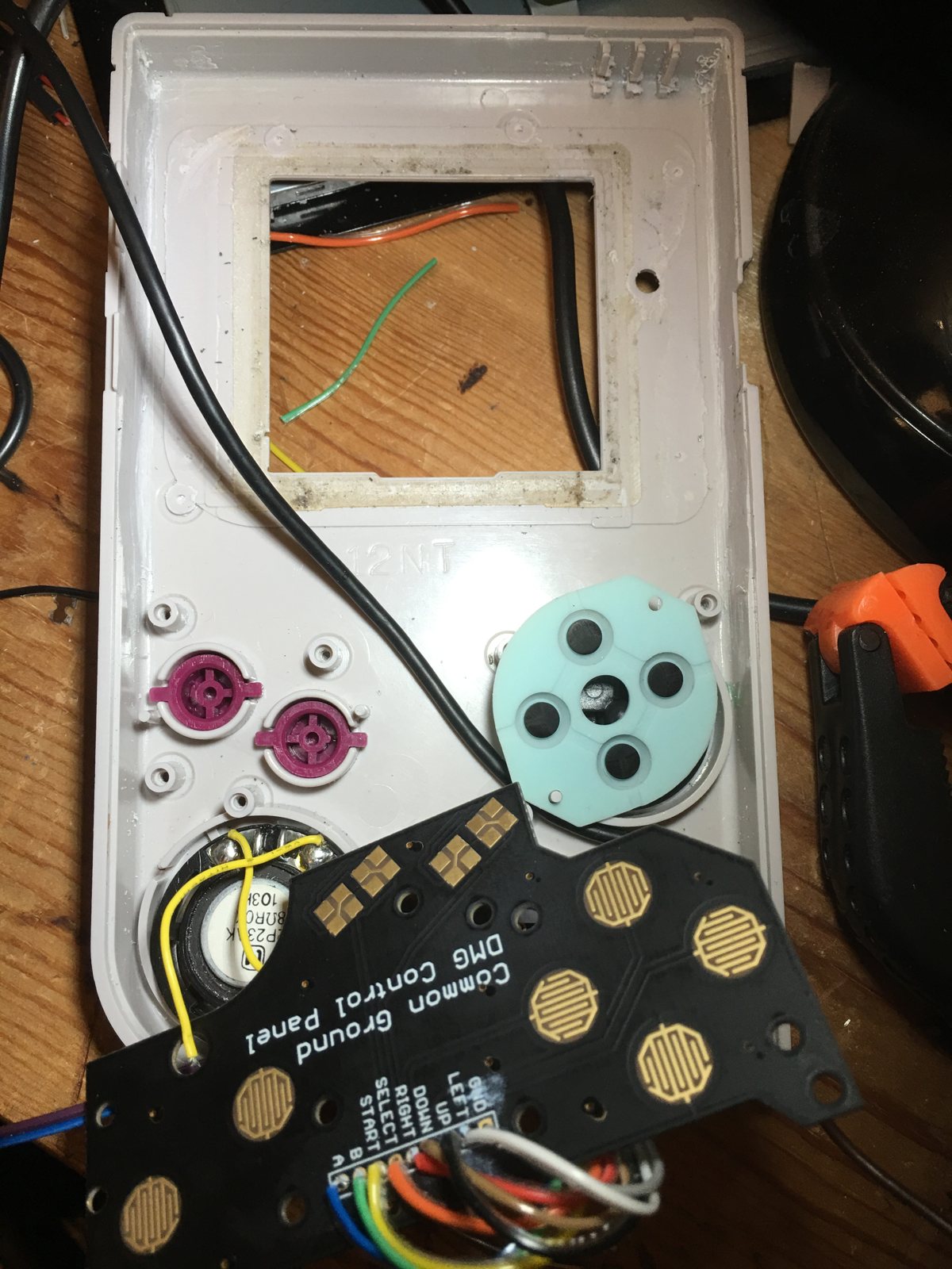
Plan B was the Common Ground DMG control panel: a replacement board that fits the case perfectly, keeps the original rubber buttons, and gives you proper pads to solder to.
A Teensy 3.1 sits underneath and turns the button presses into USB keyboard presses, a signal the Pi understands straight away.

3 Slim the Pi
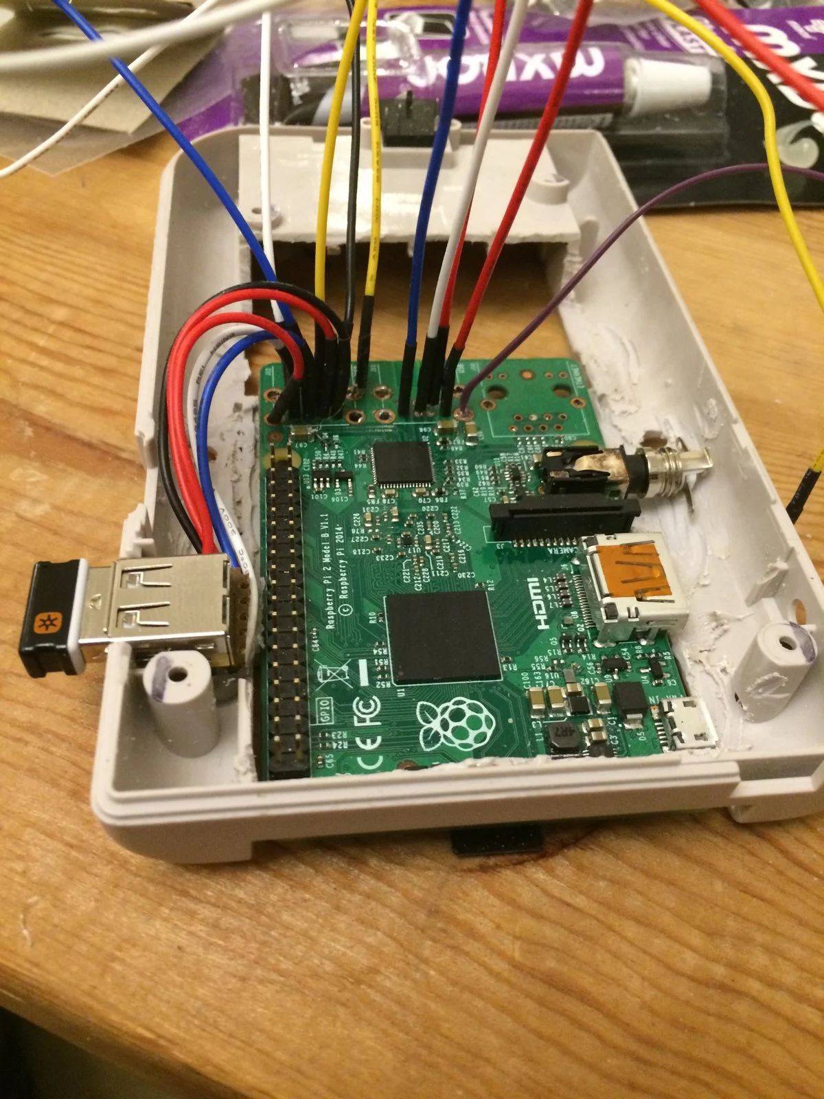
A full-size Pi 2 won’t fit, so the USB and Ethernet ports had to come off. It’s fiddly, and I only managed it on my second attempt.
There are lots of videos showing how. Watch a few first, and don’t be upset if you break a Pi.


4 Make room
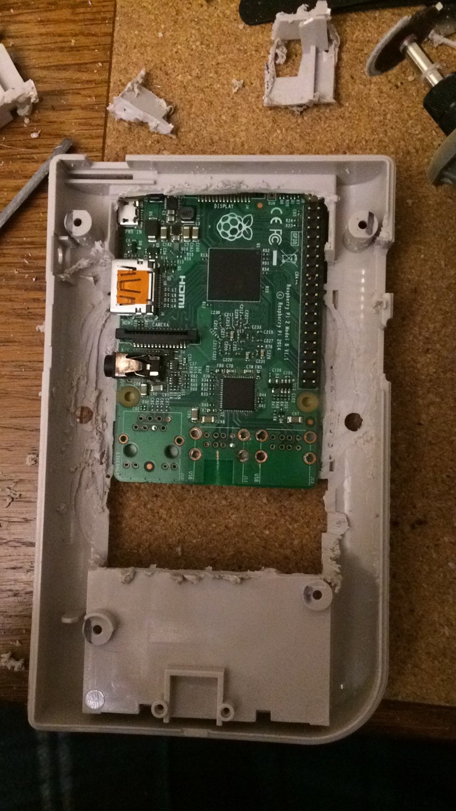
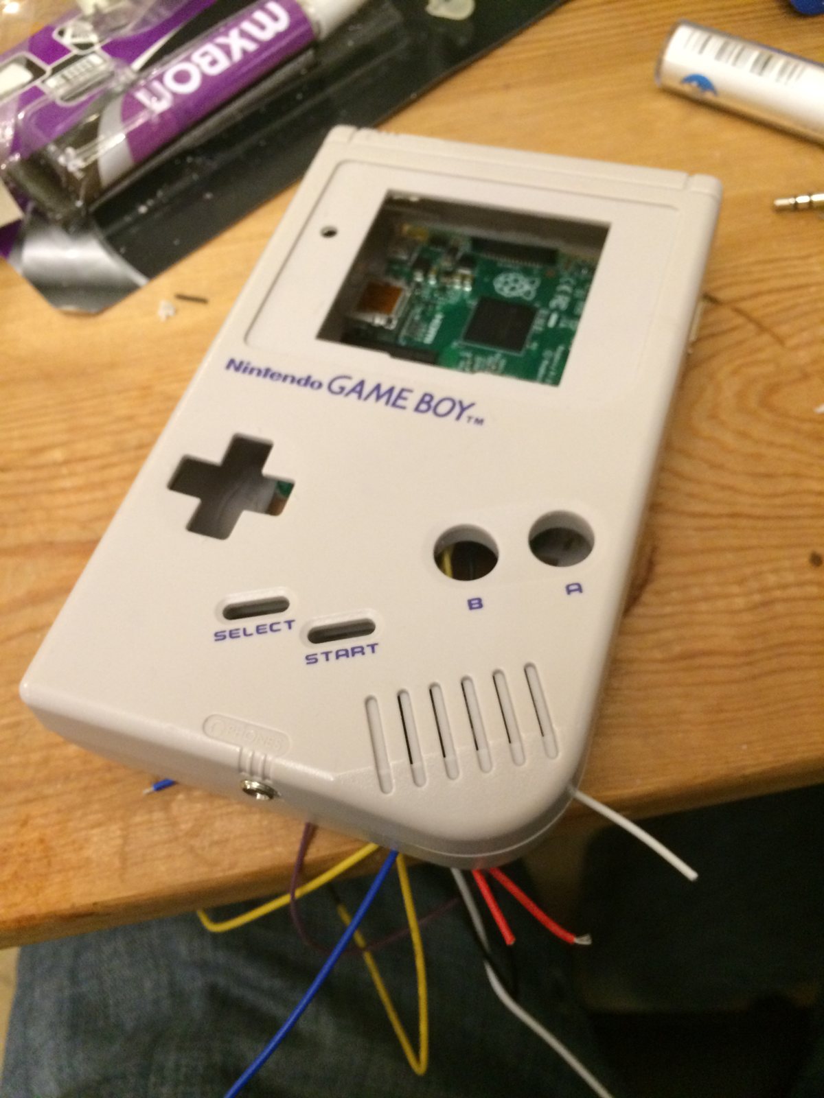
I tried several layouts before settling on the Pi sitting behind a blanked-out cartridge, so the memory card is still reachable from the cartridge slot.
Then the excavation began: a Dremel to clear the internal posts and walls, and a fine razor saw to open up the screen window. Do this somewhere well ventilated. The plastic stinks.

5 Choose a screen
I started with an Adafruit PiTFT. It plugs into the Pi’s GPIO header and is nice and sharp, but it skips some of the Pi’s video processing, so the frame rate was too low for some of the games I wanted to play.
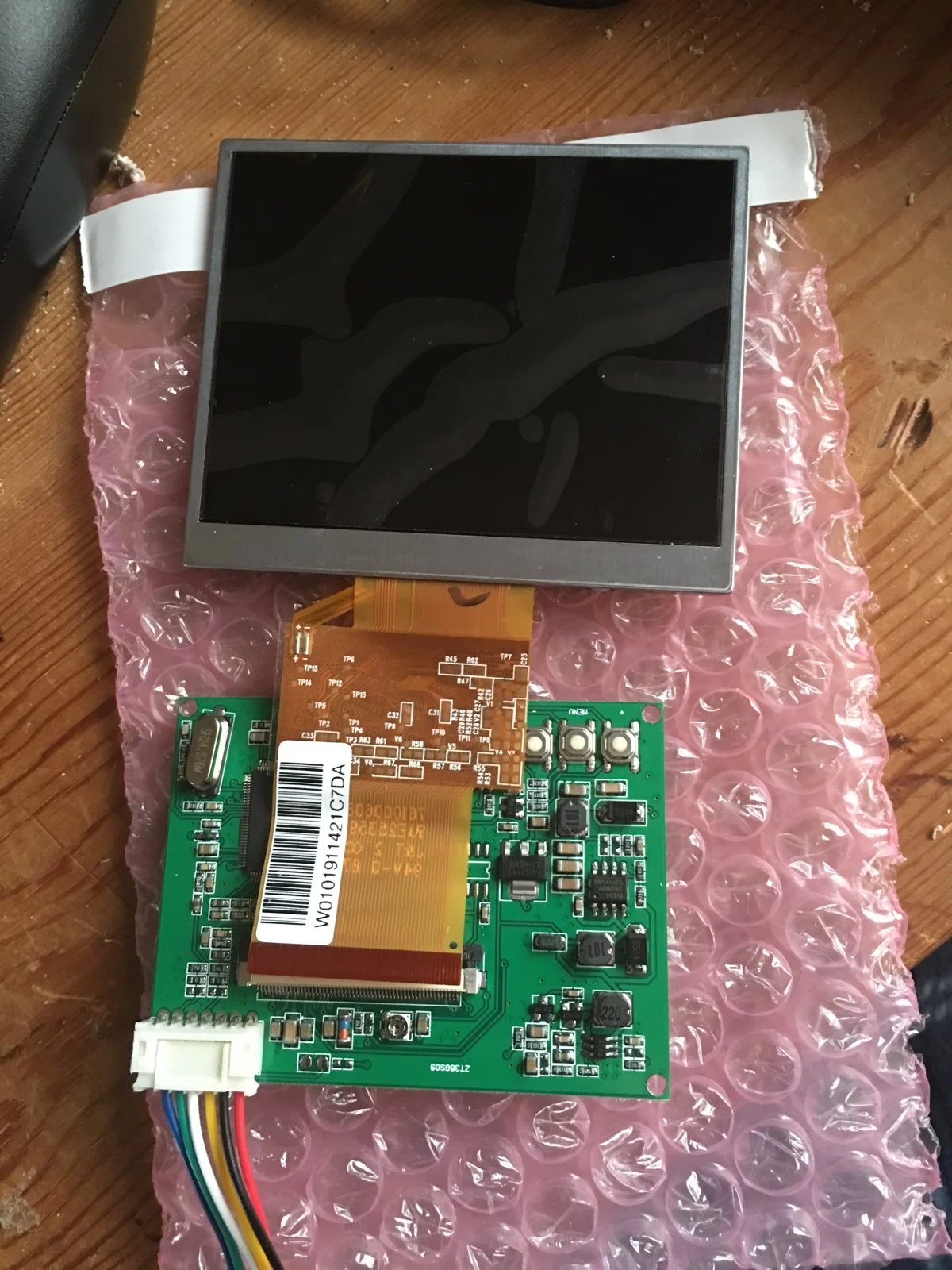
After a lot of head-scratching I switched to a composite screen originally designed for in-car use. It wants 12 volts, but remove its power step-down chip and bridge a couple of points (Adafruit has a guide) and it runs happily off 5V.


6 Power and sound
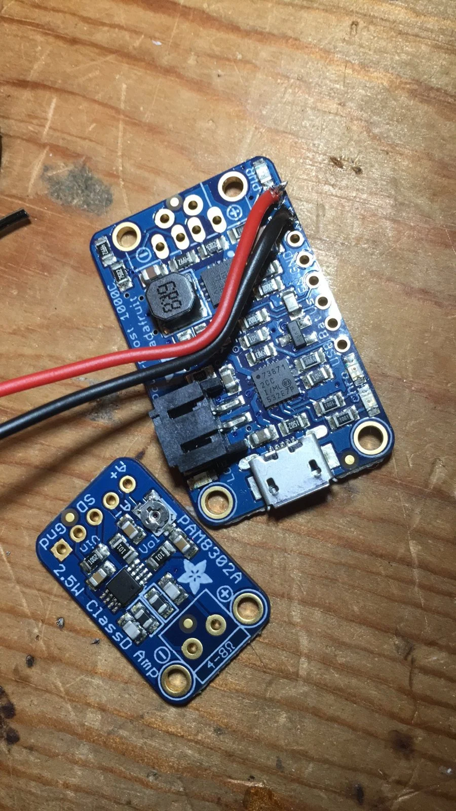
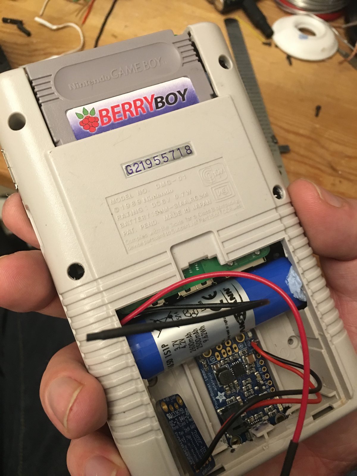
A 2,500mAh lithium-ion battery feeds an Adafruit PowerBoost 1000C. It charges the battery, boosts its 3.7V up to the 5V everything needs, and switches seamlessly between USB power and the battery.
An Adafruit mono amp drives the original Game Boy speaker nicely.
7 Close it up
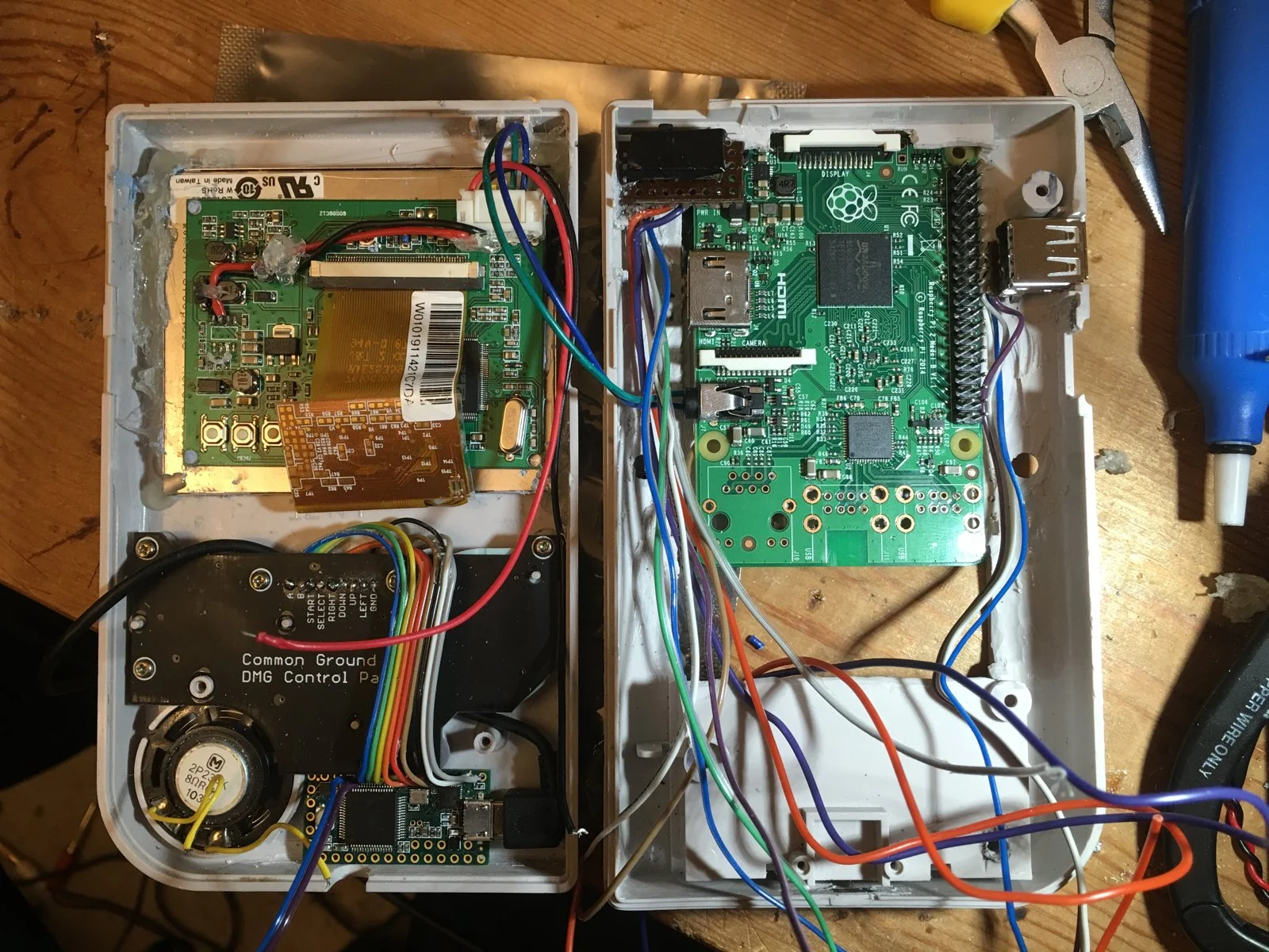
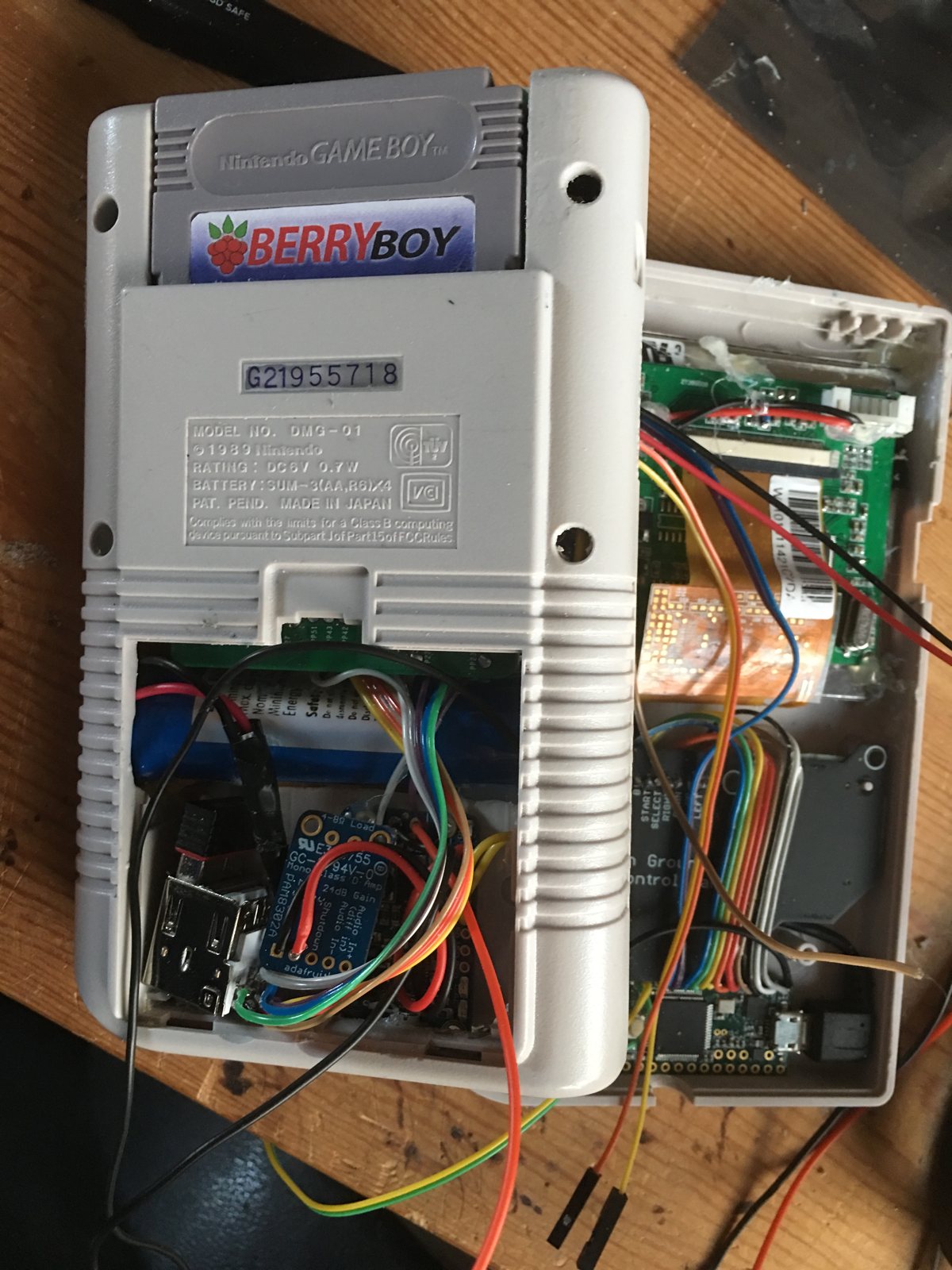
This is where it gets complicated. Wires seem to be everywhere, so I tried to stay logical and route things as neatly as I could.
Epoxy putty built up the original screw posts so the case screws back together, and scraps of blank circuit board hold the switch and USB socket in place. And yes, it closed.
The finished BerryBoy
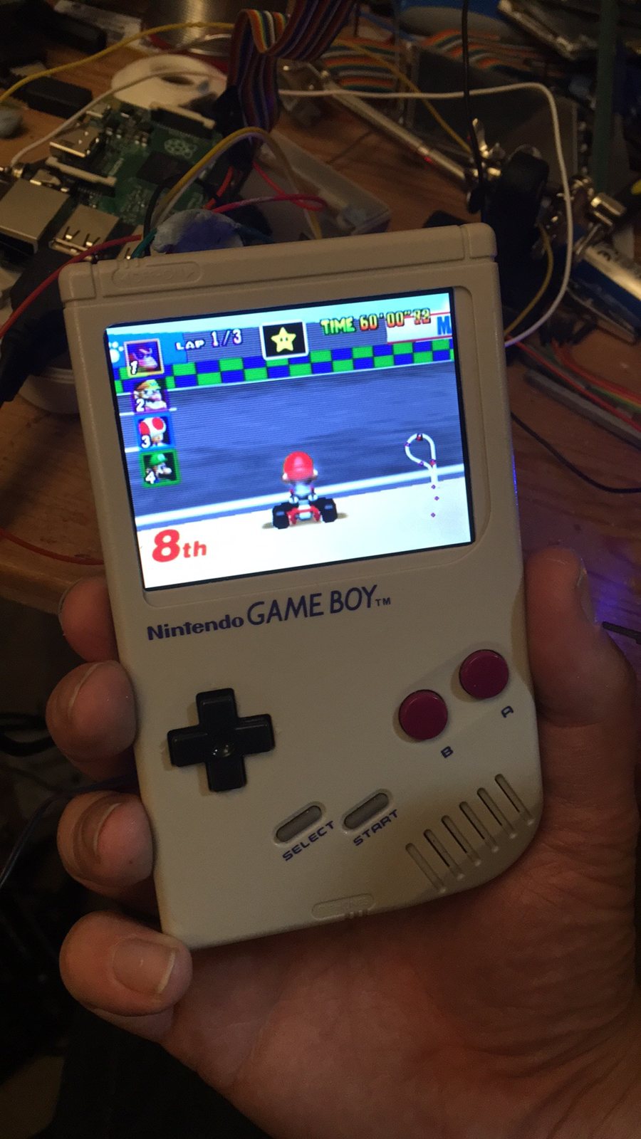
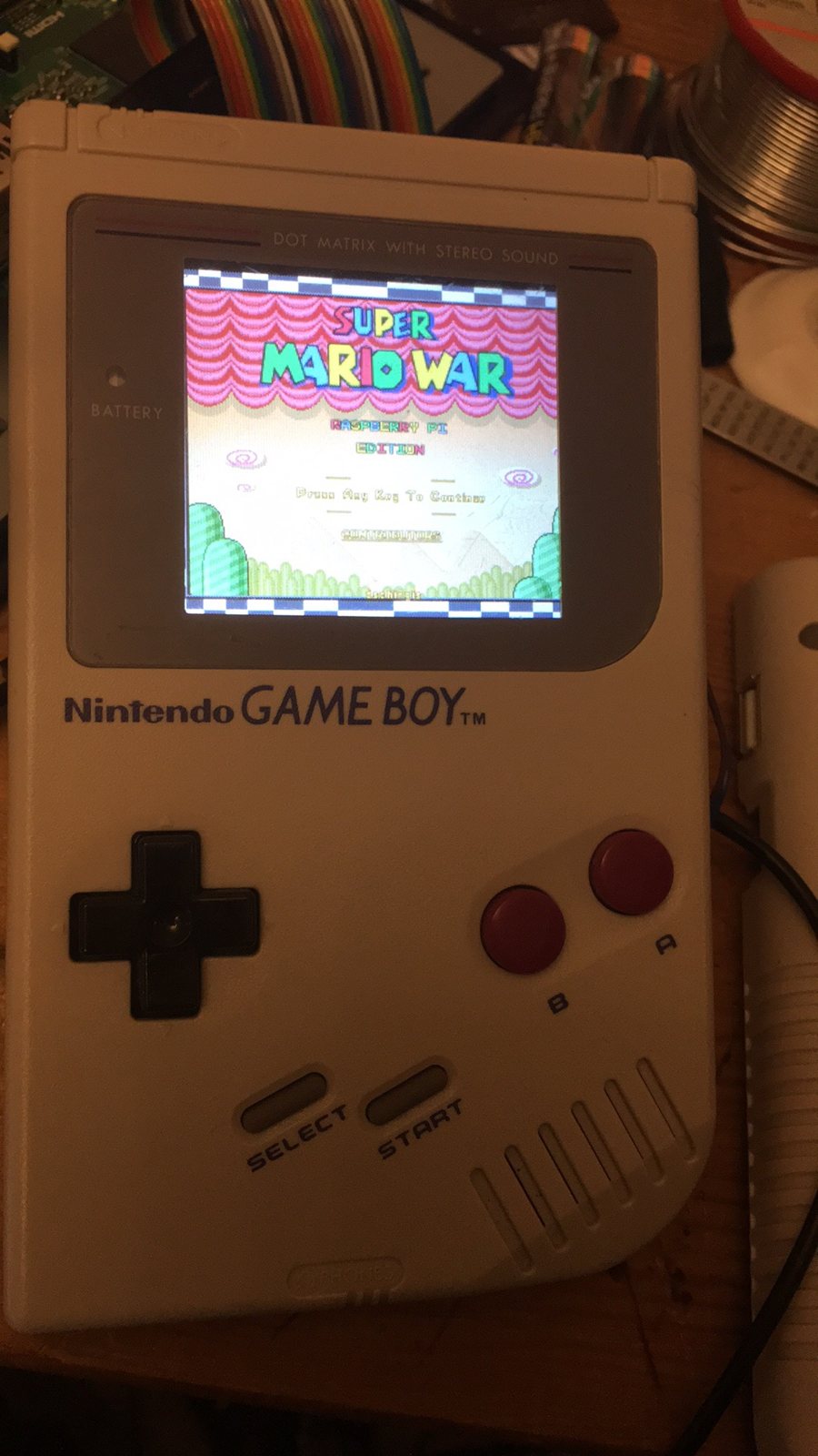
From the outside it’s a Game Boy. There’s a micro-USB jack for charging, a full-size USB port on the side for memory sticks, keyboards and mice, and a blanked-out cartridge with its own BerryBoy label. The Pi sits right behind it, so the memory card is still easy to get to.
The battery cover still opens. I modified it to hold two USB ports (one with a Wi-Fi dongle in it), the amp and the charging board.
I kept the original power switch, which I really wanted to do, but it works the wrong way round. I assumed I’d make a circuit to switch on and break it to switch off, but the charging board works the other way, and I didn’t want to just disconnect the battery or it couldn’t charge while off. Only a couple of people have noticed so far.
Parts
- Raspberry Pi 2, running RetroPie
- A faulty Game Boy (DMG-01) for the case
- Common Ground DMG control panel (Kitsch-Bent)
- Teensy 3.1 microcontroller
- Adafruit 3.5″ composite screen, converted to 5V
- Adafruit PowerBoost 1000C
- Adafruit mono amplifier
- 2,500mAh 3.7V lithium-ion battery
- USB sockets: one for the side, a double one inside the battery cover
- Plastic epoxy putty, hot glue and scraps of blank PCB
Tools
- Temperature-controlled soldering iron with a few tips
- Desoldering pumps (practise on a junk board first)
- Rotary tool with cutting and grinding bits
- A hobby vice, helping hands and small clamps
- Fine razor saw, hobby knives and files
- Wire cutters and strippers
If you build one
- Small screens: RetroPie’s game lists are hard to read at this size. Install the “Simple” theme and make the console text bigger.
- Plan the power switch before you glue anything in. Check how your charging board expects to be switched off.
- Battery: 2,500mAh gives me a couple of hours. I couldn’t fit a bigger one in; if you manage it, let me know.
- Still on my to-do list: a couple of shoulder buttons on the back, and a volume control. Over ten years on, still on the list.
Be careful: this involves soldering, cutting plastic and lithium batteries. Only use tools you’re confident with, work somewhere well ventilated, and please do your own research before starting something like this.
Build and photos by Stuart Fox, 2015. Parts and several guides from Adafruit. Watch the full video on YouTube.
Composer for TV and film. If you're working on something, I'd love to hear about it.